Hydraulic Flow Demonstrator - Clear Acrylic Flow Channel 77mm X 150mm X 1100mm | Adjustable Bed Height, Mobile Metal Frame, Diverse Hydraulic Structures
Price: 100 INR / Unit
Get Latest Price
Minimum Order Quantity :
1 Unit
Brand Name :
Teknik
In Stock
Product Specifications
| Product Type | Hydraulic Flow Demonstrator |
| Application | Hydraulic Machinery and Power Tools |
| Usage | Hydraulic Machinery and Power Tools |
| Supply Ability | 100 Per Week |
| Delivery Time | 1 Week |
| Sample Available | Yes |
| Sample Policy | Sample costs shipping and taxes has to be paid by the buyer |
| Packaging Details | carton box, export quality also available |
| Main Export Market(s) | Middle East, Asia, Africa |
| Main Domestic Market | All India |
| Certifications | ISO 9001, 14001 ,CE |
Product Overview
Key Features
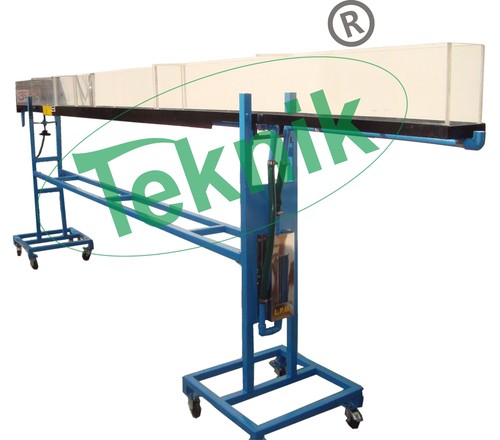
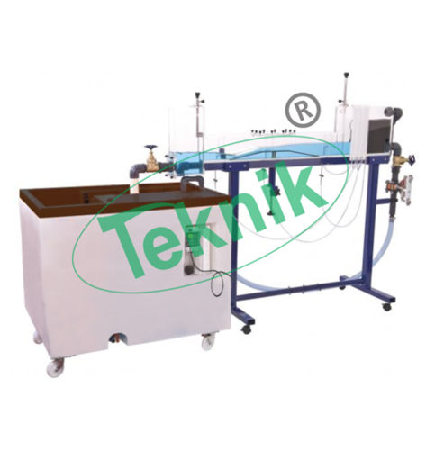
The flow channel of the Hydraulic Flow Demonstrator is constructed using clear acrylic for visibility and is supported by a floor-standing, metal frame fitted with castors for mobility. The flow channel consists of an inlet tank with overflow and flow stilling arrangement, a rectangular working section and a discharge tank. Control valves and adjustable weirs allow the flow conditions to be varied independently at the entry to and exit from the working section. The working section can be flooded to create a closed conduit or operate partially filled as an open channel. The most important feature of this equipment is the adjustable section of the bed which together with its transition section (ramps) may be raised and lowered using an external actuator while the water is still flowing. This facility affords a striking demonstration of the significance of channel critical depth.
DEMONSTRATION CAPABILITIES
Closed Conduit Flow
Application of the Bernoulli and Continuity equations to converging and diverging flow
Effect of gradual and sudden changes in cross section (energy losses)
Using a contraction as a flow-measuring device
Using a Piton tube to measure velocity / velocity profile
Flow through a culvert
Open Channel Flow
Flow beneath an undershot weir (sluice gate)
Flow over sharp-crested, broad-crested and ogee weirs
Using hydraulic structures to measure flow in an open channel
Effect of changes in upstream and downstream water level
Characteristics of clinging, aerated, depressed and drowned napes
Subcritical critical and supercritical flow/ depth.
Changes in specific energy and control imposed by the minimum energy condition
Characteristics of hydraulic jumps
Force and energy conditions in a hydraulic jump
Flow patterns associated with hydraulic jumps
Flow over drop structures / energy dissipation
Changes in flow profile in relation to the Froude Number (predicting flow conditions in an open channel)
Observation of flow patterns associated with flow around hydraulic structures
Velocity of gravity waves in shallow water / Formation of surface waves near critical depth
Project work evaluation of user-constructed hydraulic structures
TECHNICAL SPECIFICATIONS
Maximum operating flow rate: 1.6 l/s
A floor-standing flow channel for use with a hydraulics bench
Working section 77mm wide 150mm high and 1100mm long
Clear acrylic sides for good visibility of flow patterns created
Stilling arrangement at inlet to promote smooth flow into the working section
Section of bed can be elevated continuously and locked at the required height
Discharge tank incorporates flow-control valve for convenience in setting up
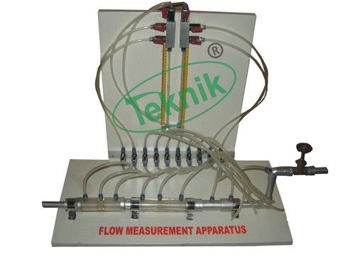
Total and static heads indicated on multi-tube manometer connected to Piton tubes and static tapings at three locations in working section
Piton tubes mounted through bed of channel for ease of priming and height adjustment (can be traversed from floor to roof to measure velocity profile)
Transparent scales allow measurement of all important heights and levels
Models of hydraulic structures supplied include undershot weir (sluice gate) at the inlet, overshot weir at the outlet, sharp-crested weir, broad-crested weir (also used to create a culvert) and ogee weir
Suitable for project work with alternative hydraulic structures (user created)
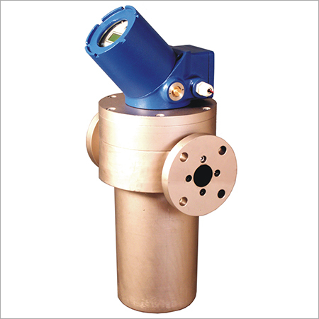
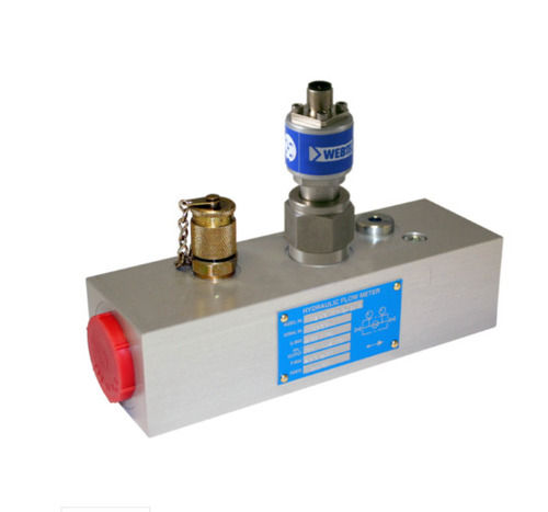
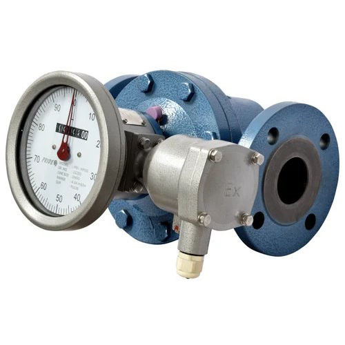
Optional direct reading flow meter to aid setting up of demonstrations
Company Details
Business Type
Exporter, Manufacturer, Distributor, Supplier, Trading Company, Wholesaler, Retailer, Dealer, Fabricator, Producer
Employee Count
25
Establishment
1973
Working Days
Monday To Saturday
GST NO
06ACMPJ7244B1ZS
Certification
ISO 9001 : 2015
Related Products
Explore Related Categories
Seller Details

GST - 06ACMPJ7244B1ZS
Ambala Cantt, Haryana
Ceo
Mr Vikas Jain
Members since
13 Years
Address
Plot No. 73, Vikaspuri, Industrial Area, Ambala Cantt, Haryana, 133001, India
hydraulic flow meter in Ambala Cantt
Report incorrect details


